Harmonics and Flicker Testing: What It Is, Why Products Fail Late, and How to Test In-House

Harmonics and flicker are conducted emissions — disturbances a product pushes back onto the mains supply rather than radiates through the air. If your product connects to the mains, it will likely need to meet limits for harmonic current emissions and voltage flicker before it can be placed on the EU and UK market. They are also among the emissions most often discovered late — at the test house, weeks before launch. This guide explains what harmonics and flicker are, which IEC 61000-3 standards apply, how to measure them correctly, and how to bring the whole test in-house.
What are harmonics and flicker?
Harmonic current emissions happen because many modern loads are non-linear. Switch-mode power supplies, chargers and motor drives draw distorted, non-sinusoidal current from the mains, and that distortion is made up of harmonics — currents at multiples of the 50 Hz supply frequency. Draw too much harmonic current and you load the supply network unevenly and interfere with other equipment on the same circuit, which is why the limits exist.
Voltage flicker is a related problem with a different symptom. Loads that draw rapidly fluctuating current — a motor starting, a heating element switching, a welder striking — cause small, repeated dips in the supply voltage. Those dips modulate the light output of lamps on the same circuit, producing the visible flicker the standards are designed to keep within human tolerance. In short: harmonics are a current-quality problem, and flicker is a voltage-quality problem.
Why do harmonics and flicker catch products out late?
Most EMC failures that surface late in a project are not radiated emissions — they are conducted ones. Radiated behaviour tends to be checked early and often on the bench, whereas harmonics and flicker are frequently left until formal certification. That is where the surprises appear.
For harmonics, exceeding the limits means the product fails certification — often discovered at the test house, when a fix may mean a hardware change to the input stage rather than a quick tweak. For flicker, the assessment runs over long-duration measurements using two indices: the short-term flicker severity Pst, measured over 10 minutes, and the long-term severity Plt, derived from a sequence of Pst values over 2 hours. That length makes flicker one of the most time-consuming compliance steps — and a slow one to iterate if you are booking test-house time for every attempt.
Which standards apply to harmonics and flicker testing?
Four product standards set the emission limits, split by the equipment's current rating:
- Harmonic current emissions: IEC 61000-3-2 covers equipment drawing up to 16 A per phase; IEC 61000-3-12 covers equipment above 16 A and up to 75 A per phase.
- Voltage changes, fluctuations and flicker: IEC 61000-3-3 covers equipment up to 16 A per phase; IEC 61000-3-11 covers equipment up to 75 A per phase that is subject to conditional connection.
Two further standards define how the measurement itself is made: IEC 61000-4-7 specifies the instrumentation for harmonic measurement, and IEC 61000-4-15 specifies the flickermeter used to assess flicker. A compliant test has to satisfy both the product limits and the prescribed measurement method — one without the other is not enough.
How do you test harmonics and flicker properly?
A valid measurement depends on three things. Get any of them wrong and your results are likely to deviate considerably from those obtained at the certification stage:
- A measurement instrument compliant with IEC 61000-4-7 and IEC 61000-4-15. This is what actually quantifies the harmonic currents and computes the flicker indices.
- A low-distortion AC source that stays within the IEC source requirements throughout the test. The standards limit how much distortion the test voltage itself may contain. A noisy source contaminates the measurement and can mask or exaggerate a result.
- An accurate flicker reference impedance. Flicker is assessed against a standardised reference impedance, so the network used has to match the standard and be applied correctly.
You can assemble those three from separate instruments and build a compliant setup. In practice, though, that means bench space, careful configuration, and time spent swapping impedance networks between tests — which is where an integrated system starts to earn its place.
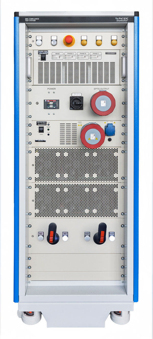
Testing harmonics and flicker in-house: the SmartTS-HFI
For teams who would rather find failures in their own lab than at the test house, Pacific Power Source — for whom Caltest is the UK distributor — offers the SmartTS-HFI, which brings full-compliance harmonics and flicker testing onto a single turnkey platform. It combines the three requirements above in one system:
- Single- and three-phase configurations from 16 A to 75 A per phase, covering IEC 61000-3-2, IEC 61000-3-3, IEC 61000-3-11 and IEC 61000-3-12.
- A precision HFMM measurement module implementing IEC 61000-4-7 and IEC 61000-4-15.
- Software-selected flicker impedance, so there are no manual network swaps between tests.
- Guided workflows with instant pass/fail and one-click, audit-ready reports.
- Real-time instantaneous flicker (IFS) visibility, which helps predict Pst early and cut long flicker runs short when a result is clearly heading to a fail.
You can also add the EPTS module — now or later, since the cabinets are pre-wired — for full-compliance voltage dips and interruptions testing to IEC 61000-4-11, IEC 61000-4-34 and IEC 61000-4-29. The practical payoff is faster testing times and, more importantly, catching failures in your own lab rather than discovering them weeks into a test-house booking.
Caltest Instruments is the UK distributor for Pacific Power Source, based in Petersfield, Hampshire, with more than 20 years supplying power test and measurement equipment and an in-house UKAS-accredited calibration laboratory.
Frequently asked questions
What is the difference between harmonics and flicker?
Harmonics are distortions in the current a product draws from the mains, caused by non-linear loads such as switch-mode power supplies and motor drives. Flicker is the visible variation in lamp brightness that occurs when a fluctuating load produces small, repeated dips in the supply voltage. Harmonics are a current-quality problem; flicker is a voltage-quality problem, and each has its own IEC 61000-3 standards.
Which IEC standards cover harmonics and flicker testing?
Harmonic current emissions are covered by IEC 61000-3-2 (up to 16 A per phase) and IEC 61000-3-12 (above 16 A, up to 75 A per phase). Voltage flicker is covered by IEC 61000-3-3 (up to 16 A per phase) and IEC 61000-3-11 (up to 75 A per phase, conditional connection). The measurement methods are defined by IEC 61000-4-7 and IEC 61000-4-15.
What is IEC 61000-3-2?
IEC 61000-3-2 is the product standard that sets limits for harmonic current emissions from equipment with an input current up to 16 A per phase. It sorts equipment into classes and defines the maximum harmonic currents each may draw, to protect the supply network and other connected equipment.
What causes voltage flicker?
Voltage flicker is caused by loads that draw rapidly fluctuating current — for example motors starting, heaters switching or welders striking. The changing current produces small, repeated dips in supply voltage, which modulate the brightness of lamps on the same circuit and are perceived as flicker.
Why do products fail harmonics and flicker testing late in a project?
Because they are conducted emissions that are often left until formal certification rather than checked on the bench early. A failure found at the test house can require a change to the product's input stage, which is expensive and slow to fix so close to launch. Testing earlier, in-house, reduces that risk.
Can you test harmonics and flicker in-house?
Yes. With a measurement instrument compliant with IEC 61000-4-7 and IEC 61000-4-15, a low-distortion AC source that meets the IEC source requirements, and an accurate flicker reference impedance, harmonics and flicker can be tested in-house. Integrated systems such as the Pacific Power Source SmartTS-HFI combine all three on one platform.
What is the difference between Pst and Plt?
Pst is the short-term flicker severity, measured over 10 minutes; Plt is the long-term flicker severity, derived from a sequence of Pst values over 2 hours. Both must stay within the limits set in IEC 61000-3-3 or IEC 61000-3-11. Because Plt spans two hours, flicker is one of the most time-consuming parts of compliance testing.
Talk it through with an engineer
Tell us what your applications are and we'll support you in choosing an appropriate test system configuration — phases, current rating and compliance level. Contact the Caltest team, or explore the SmartTS-HFI and the wider Pacific Power Source range.