Test and Calibration Requirements Across the SMR Lifecycle: From Component Qualification to Grid Connection
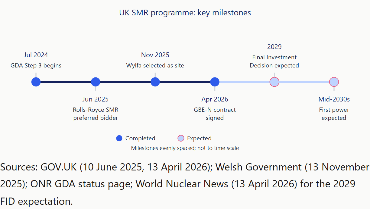
An SMR programme asks its supply chain for two things at a scale most UK suppliers have not met before: test evidence that repeats from one factory-built unit to the next, and measurement results an auditor can trace back to national standards. The UK programme is now moving fast enough to make both a practical question. Wylfa was selected as the first site in November 2025, and Great British Energy – Nuclear (GBE-N) signed its contract with Rolls-Royce SMR in April 2026. A Final Investment Decision is expected in 2029, according to World Nuclear News, and the government aims to connect projects to the grid in the mid-2030s with 70% of the fleet's value supplied by UK-registered companies.
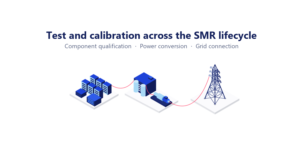
The test work falls into three stages, each with its own standards and methods: qualifying components and systems, accepting the power-conversion and plant electrical systems, and proving grid compliance. One discipline runs through all three, and that is calibration. In this article, SMR test equipment means the programmable sources, loads, electrical safety analysers, power analysers and grid simulators used to generate qualification, acceptance and grid-compliance evidence, together with the calibration that makes that evidence traceable.
Key Takeaways
- The UK SMR programme has a site (Wylfa, November 2025), a signed GBE-N contract (April 2026) and a Final Investment Decision expected in 2029. GBE-N reports that more than 70% of nearly £900 million awarded since 2023 has gone to UK-registered companies, so UK suppliers are likely to be asked for documented, repeatable test evidence.
- Qualification testing is framed by IEC 61226:2020 (safety categorisation), IEC/IEEE 60780-323:2016 (qualification of electrical equipment important to safety) and IEC 62003:2020 (EMC, drawing on the IEC 61000 series), under a quality system that is likely to be ISO 19443:2018 on top of ISO 9001:2015.
- A 470 MWe unit is a Type D, transmission-connected generator, so the GB Grid Code European Connection Conditions are expected to apply rather than EREC G99. Those conditions require operation across 47 to 52 Hz, fault ride-through of up to 140 ms, and witnessed testing under NESO's EON, ION and FON process.
- Calibration is the common thread: ISO/IEC 17025:2017 clause 6.5 traceability, a published UKAS schedule that defines exactly what is accredited, and on-site capability so that equipment does not have to leave a rig or a licensed site.
Why the UK SMR programme is a test-equipment story
The decisions of the last fifteen months have turned the UK SMR programme from a policy into a procurement pipeline. In June 2025 the government selected Rolls-Royce SMR as preferred bidder and renamed Great British Nuclear as Great British Energy – Nuclear. Wylfa on Anglesey was chosen as the site of the first station in November 2025, initially for three reactors. In April 2026 GBE-N and Rolls-Royce SMR signed their contract, by which point "over £350 million in contracts across the supply chain" had already been placed. The 470 MWe design remains in Step 3 of the Office for Nuclear Regulation's Generic Design Assessment, the final step; ONR had not published a completion at the time of writing.
The supply-chain figures explain why test and calibration capacity matters. GBE-N reported in June 2026 that of nearly £900 million awarded since 2023, more than 70% went to UK-registered companies, against a programme target of 70% of the fleet's value. Exports add volume: Rolls-Royce SMR has been selected for three 470 MW reactors in Sweden and holds an early works contract in Czechia. A fleet built in factory-made modules, for several sites in several countries, is likely to ask each supplier for the same thing: test evidence that is repeatable from unit to unit and documented well enough to survive a licensee's or a regulator's audit.
Fusion is running a parallel programme with the same supply-chain shape. UK Fusion Energy Ltd describes STEP as "a prototype plant we are building and will operate at West Burton... from 2040", and its April 2026 strategy reports 854 suppliers engaged, 84% UK-based, and £125.5 million in industry spending.
Across both, the work divides into three stages: qualifying components and systems, accepting power-conversion and plant electrical systems, and proving grid compliance. The methods differ at each stage. What connects them is that every measurement has to be traceable.
Standards by lifecycle stage
- ISO 19443:2018 (on ISO 9001:2015). Component qualification: Supplier QMS; Factory and site acceptance: Supplier QMS; Grid compliance: Graded approach; In-service: Records
- IEC 61226:2020. Component qualification: Sets category; Factory and site acceptance: Informs grading; In-service: Informs grading
- IEC/IEEE 60780-323:2016. Component qualification: Qualification; In-service: Maintaining qualification
- IEC 62003:2020 with IEC 61000 series. Component qualification: EMC testing; Factory and site acceptance: Immunity checks
- IEC 61000-4-30:2025. Factory and site acceptance: Power quality; Grid compliance: Power quality; In-service: Monitoring
- ISO/IEC 17025:2017. Component qualification: Calibration chain; Factory and site acceptance: Calibration chain; Grid compliance: Calibration chain; In-service: Calibration chain
- GB Grid Code ECC. Factory and site acceptance: Design basis; Grid compliance: Type D units; In-service: Ongoing compliance
- EREC G99. Grid compliance: Distribution-connected only; In-service: Distribution-connected only
Stage 1: Component and system qualification
Qualification asks a supplier to show that equipment important to safety will perform under the service conditions it will meet, and to keep that evidence for the life of the plant. For electrical, instrumentation and control suppliers this is where the nuclear-specific standards concentrate, so it is worth being precise about which one does what.
Which standards drive qualification
The sequence starts with categorisation. IEC 61226:2020 "establishes... a method of assignment of the functions specified for the plant into categories according to their importance to safety", the familiar categories A, B and C. That category then decides how much qualification the equipment supporting the function needs. IEC/IEEE 60780-323:2016 sets out the requirements for qualifying, maintaining and extending the qualification of electrical equipment important to safety; a joint revision is in progress, so check the edition a specification cites. Electromagnetic compatibility is handled by IEC 62003:2020, which frames EMC test requirements for instrumentation, control and electrical equipment by reference to "the applicable IEC standards (principally the IEC 61000 series)". In practice that means a generic industrial immunity standard such as BS EN IEC 61000-6-2:2019 is likely to appear in a test plan alongside the plant-specific requirements.
Above the technical standards sits the quality system. ISO 19443:2018 adds nuclear-specific requirements (a graded approach, safety culture, control of items and services important to nuclear safety) on top of ISO 9001:2015. A second edition is at committee-draft stage, so treat 2018 as current but not final. On the licensee's side, ONR Licence Condition 17 requires "adequate quality management arrangements in all matters which may affect safety", and those arrangements flow down to suppliers through procurement. ONR's technical assessment guide NS-TAST-GD-077 covers supply chain management for nuclear safety related items and services, which is a useful read before a licensee's quality team arrives.
What the testing looks like in practice
For a power supply, a motor drive, a UPS module or a control cabinet, qualification testing is mostly powered testing, run long enough to reveal drift. Typical elements include:
- Endurance and margin testing at rated, minimum and maximum input voltage, with the output loaded through its full range
- Source and sink cycling where the equipment both delivers and absorbs energy, as battery systems and regenerative drives do
- Dielectric withstand, insulation resistance and ground bond checks before and after environmental or ageing sequences
- Efficiency and power-quality measurement, so thermal and harmonic behaviour is characterised rather than assumed
The common failure mode is rarely a failed test. It is a passed test that cannot be reproduced eighteen months later because the source, load or analyser was not in calibration at the time, or the certificate did not state an uncertainty. That is a records problem, and ONR Licence Condition 28 ("adequate arrangements for the regular and systematic examination, inspection, maintenance and testing of all plant which may affect safety") is one reason a licensee is likely to ask about it.
Equipment for qualification testing
- Programmable DC for rated and margin testing: high-power DC supplies, for example the Elektro-Automatik PSI 10000 (30 kW in 4U; up to 2000 VDC; up to 1000 ADC)
- Source and sink in one unit: bidirectional DC supplies such as the Elektro-Automatik PSB 10000 (bidirectional; 30 kW; up to 2000 VDC; up to 1000 ADC)
- Loading the output: electronic loads, DC and AC
- Safety tests: electrical safety analysers such as the Associated Research HypotULTRA (AC/DC hipot, insulation resistance, ground continuity and ground bond in one 2U unit; up to 5,000 VAC and 6,000 VDC). Our EN 61010 explainer covers the safety standard that applies to the test equipment itself
- Efficiency and harmonics: power analysers
Stage 2: Power conversion and plant electrical systems
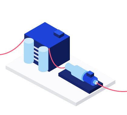
Between the reactor and the grid sits a conventional-looking electrical plant: turbine-generator auxiliaries, converters, motor drives, UPS and battery systems, switchgear, and the essential supplies that keep safety systems powered. Much of it is typically acceptance-tested twice, once at the factory and again on site, and both tests are stronger when the supply conditions are controlled rather than taken from whatever the works mains happens to be doing that afternoon.
One of the most useful factory acceptance tests is one that runs the equipment under abnormal supply conditions on purpose. Sustained voltage deviation, frequency offsets, harmonic distortion, dips and short interruptions are all conditions the plant will meet, and a programmable AC source lets you apply each one as a repeatable profile and record the response. Power-quality measurement on the equipment's own input and output, using the methods of IEC 61000-4-30 (a new edition was published in 2025), gives that response a common language between supplier and customer. Our post on harmonics and flicker testing explains the measurement side in more detail.
Accuracy class deserves a paragraph because it decides whether an efficiency claim can be defended. If a converter's efficiency is in the high nineties per cent, the quantity you are resolving is the small percentage of loss, and each power measurement at input and output carries its own uncertainty. With ±0.1% class instruments, a meaningful share of that loss can sit inside the combined uncertainty. Move to a ±0.05% or ±0.03% class and the same test resolves a design change that was previously invisible. Our Yokogawa power analyser guide works through this logic with numbers.
Regeneration matters at this power level for a practical reason. A 30 kW or 300 kW test that dissipates its energy as heat needs cooling capacity and pays for the electricity twice. A regenerative source-and-load pair returns most of the absorbed energy to the works supply instead, which makes the long endurance runs qualification asks for easier to justify.
Equipment for power-conversion acceptance testing
- Regenerative AC and DC sources: see our AC and DC sources page, including the Pacific Power Source AGX Series (fully regenerative 4-quadrant AC/DC power source; up to 24 kW, scalable to 1.296 MVA) and, at higher power, the AZX Series (30–55 kW, to 440 kW parallel) and GSZ Series (up to 1.1 MW)
- Regenerative loads: for example the Pacific Power Source RLS Series (regenerative 4-quadrant AC and DC load; up to 24 kW, scalable to 1.296 MVA/MW) and ELZ Series (regenerative AC/DC load up to 1.1 MW), and on the DC side the Elektro-Automatik ELR 10000 (regenerative DC load; 30 kW; recovers energy back to the grid)
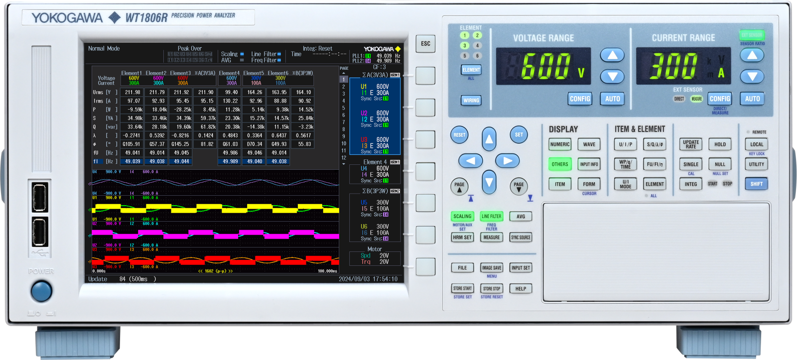
- Power analysers: Yokogawa WT1800R (up to six input elements; ±0.05% power accuracy; harmonics to the 500th order) and WT5000 (basic power accuracy ±0.03%; up to seven input elements)
Stage 3: Grid connection testing
A 470 MWe unit would connect to the transmission system, and that is what decides which rulebook applies. Under the ENA's summary guide to the Requirements for Generators types, a Type D power generating module has a "Connection Point at, or greater than, 110 kV; or... below 110 kV and with Registered Capacity of 50 MW or greater". Any unit in the current UK SMR programme clears that threshold by a wide margin. EREC G99 (Issue 2, published in March 2025) governs generation connected to a distribution network, including Type D units below the transmission threshold. A transmission-connected unit is instead governed by the GB Grid Code's European Connection Conditions (ECC), administered by NESO, so that is where an SMR generator's compliance evidence will be judged.
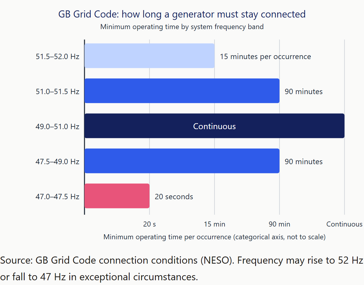
What the Grid Code asks a generator to withstand is specific. On frequency, the Grid Code connection conditions require operation across 47 to 52 Hz with a minimum duration for each band: continuous between 49 and 51 Hz, 90 minutes between 47.5 and 49 Hz and between 51 and 51.5 Hz, 15 minutes per occurrence between 51.5 and 52 Hz, and 20 seconds between 47 and 47.5 Hz. On voltage, the same conditions set ±5% at 400 kV (±10% under defined conditions), ±10% at 275 kV and 132 kV, and ±6% below 132 kV. On faults, the European Connection Conditions require ride-through of short faults of up to 140 ms, symmetrical and asymmetrical, plus a longer-duration balanced-fault profile.
Compliance is staged. NESO's compliance process issues an Energisation Operational Notification (EON), "required for first energisation (back feed)", then an Interim Operational Notification (ION), "required for first export", which carries "a schedule of unresolved issues" and "a lifetime of 24 months", and finally a Final Operational Notification (FON) "when all issues identified within the ION have been satisfactorily addressed". NESO states that "witnessed testing will be required to be undertaken with NESO". Its guidance notes for synchronous generators have the generator draft and run its own test procedures for voltage control and frequency response, with fault ride-through typically demonstrated through validated simulation models rather than deliberate site faults, an approach NESO's guidance encourages.
This is where grid simulators earn their place, and it is worth being exact about what they test. Nobody puts a 470 MWe generator on a grid simulator. What goes on the simulator is everything between the generator and the grid that has to survive the same disturbance: converters, inverters, UPS and essential-supply systems, auxiliary drives, protection and control. A regenerative grid simulator can replicate real and abnormal utility grid conditions, including low-voltage ride-through events, so a converter can be exposed to the 140 ms fault profile, the frequency excursions and the harmonic content in the laboratory, months before witnessed testing on site. At megawatt scale, ORE Catapult's 18 MVA eGrid system at Blyth has done exactly this for a 6 MW wind turbine nacelle in "static and dynamic operation modes", to "achieve grid-compliant assurance". Our posts on grid emulators for data centres and power hardware-in-the-loop testing cover the method; anti-islanding testing covers a related protection test.
Equipment for grid connection testing
- Grid simulation: grid simulators, from the Pacific Power Source RGS Series (regenerative grid simulator and 4-quadrant AC/DC power source; up to 24 kW; test capability for "IEEE 1547 and IEC 61000") through the AZX Series (to 440 kW parallel) to the GSZ Series (up to 1.1 MW); the Cinergia GE AC/DC Series (regenerative AC/DC grid emulator; up to 50 harmonics per phase) where harmonic profiles are the focus
- Recording the response: power analysers, as in Stage 2
The thread through all three: calibration you can show an auditor
Every number in the three stages above came from an instrument, and an auditor is likely to ask, sooner or later, what that instrument was compared against. ISO/IEC 17025:2017 clause 6.5 requires a laboratory to establish and maintain the metrological traceability of its measurement results. UKAS's policy document TPS 41 spells out what that means: "a documented unbroken chain of calibrations, each contributing to the measurement uncertainty", running to a national metrology institute under the CIPM MRA or to an ILAC-accredited calibration laboratory. NPL's plain-English version, from its traceability teaching poster, is that "measurement traceability is the unbroken chain of comparisons between a given measurement device and national or international standards", and that by having equipment calibrated you "compare your measurement equipment directly or indirectly with the primary standards" NPL maintains on behalf of the UK.
In a nuclear supply chain those expectations arrive through the licensee. ONR Licence Conditions 17 and 28, and the technical assessment guides its inspectors use (NS-TAST-GD-009 on examination, inspection, maintenance and testing; NS-TAST-GD-077 on supply chain management), are typically where a licensee's procurement questions come from. Two further documents help with the detail. ILAC-G24:2022 covers how to choose and review recalibration intervals: fixed interval, calendar or usage based, control charts and in-service checks are all recognised methods, and the user is expected to choose a method and review it. UKAS LAB 5 sets out what a calibration certificate must report.
Three practical points follow from this.
Scope. Accreditation is a schedule of quantities and ranges, not a badge on a building. UKAS publishes every laboratory's Schedule of Accreditation. Ours, laboratory 4432, lists an "Electrical" activity at Petersfield and "At customers premises", covering DC resistance, DC voltage, DC current, DC power, AC voltage, AC current, frequency, time period, active power, reactive power and phase angle, with a particular focus on AC power and energy. UKAS-accredited calibration is available on products covered by our Schedule of Accreditation. The distinction shows on the paperwork: "You will receive either a UKAS-accredited calibration certificate or a traceable calibration certificate, depending on the equipment type and your requirements." Ask any supplier to show you the schedule before assuming a measurement is covered.
Site access. Equipment on a licensed site or built into a fixed test rig cannot always leave. ISO/IEC 17025 clause 6.3.5 covers laboratory activities carried out at sites outside the laboratory's permanent control, and a UKAS schedule states whether site work is within scope. Our field calibration team "provides on-site UKAS ISO 17025 accredited calibration across the UK and Ireland, with international visits available by arrangement"; our article on on-site UKAS calibration explains how a visit is planned.
Downtime. On-site work removes transit time altogether. Where an instrument does have to travel, ask about turnaround and about what covers you while it is away. Rental equipment on "flexible rental periods from as little as a week to longer terms of over a year" can keep a test schedule moving. Details of laboratory and site services are on our service and calibration page.
Fusion: the same chain, higher peaks
The fusion programme shares the supply-chain shape of SMR but pushes the electrical numbers further. UK Fusion Energy Ltd plans to build and operate STEP at West Burton from 2040, with first operations targeted for the early 2040s and £1.3 billion allocated to the programme. Tokamak Energy was appointed STEP's Magnet Systems Partner under a £70 million contract in April 2026, and Tokamak Energy reports that its Demo4 magnet has "achieved 11.8 Tesla at cryogenic temperatures with seven million ampere turns". For a sense of scale on the pulsed side, JET's two flywheel generators "each provide the JET device with peak power up to 400 MW and energy up to 2600 MJ per pulse", across more than 85,000 pulses since 1983.
UKAEA's power supplies group has described its field as covering high-voltage AC distribution, pulsed AC/DC converters, capacitor banks, fast DC opening switches, fast power control for beams and RF sources, and the measurement, control and protection systems that go with them. That list reads like a test-equipment specification. Magnet and coil work wants stable high-current DC with very low drift; beam and RF work wants bipolar supplies that cross zero cleanly and respond quickly; and the associated measurement systems want the same calibration chain described above, because a magnet current that is a fraction of a percent off is a different magnet.
On the supply side that points to instruments such as the CAEN ELS NGPS Series (10 kW, to 40 kW in parallel; temperature coefficient below 1 ppm/°C) for stable high-current work and the CAEN ELS FAST-PS Series (true bipolar zero-crossing; ±30 A / ±80 V; 10 kHz update rates) for fast bipolar control, alongside the regenerative loads and high-power DC already covered in Stages 1 and 2. Accredited calibration of the DC current, voltage and power measurements those supplies depend on is the same service, whether the end use is a reactor auxiliary or a tokamak coil.
Six questions to ask a test-equipment and calibration supplier
- Which quantities and ranges are on your UKAS schedule, and what do I get for everything else? The answer tells you which of your certificates will carry the UKAS symbol and which will be traceable-only, before an auditor tells you.
- Can you calibrate on site, and to the same accreditation? A schedule that lists site activity separately from the laboratory is the evidence; a verbal yes is not.
- What is your turnaround, and what covers me while an instrument is away? Rental or loan cover is the difference between a calibration interval and a programme delay.
- Is your quality system certified, and how do you handle nuclear-grade documentation requests? ISO 9001 certification is the baseline; the useful follow-up is who owns a request for extended records, uncertainty budgets or witnessed calibration.
- Can you support the standards my test procedures cite? IEC 61000 series immunity and power-quality methods, dielectric withstand, and grid-code ride-through profiles each need specific source, load and measurement capability, and it is better to find a gap before the rig is built.
- Can you configure or integrate a test system rather than supply individual instruments? Qualification and acceptance rigs are usually a source, a load, a safety analyser and a power analyser working together; our system integration page describes how that can be done as a single project.
Frequently asked questions
Does EREC G99 apply to a small modular reactor?
Not to the generating unit itself in the current UK programme. A 470 MWe unit has a Registered Capacity far above the 50 MW Type D threshold and would connect to the transmission system, so the GB Grid Code European Connection Conditions are likely to apply, with compliance demonstrated to NESO through the EON, ION and FON process. EREC G99 governs generation connected to a distribution network, including Type D units below the transmission threshold. Site auxiliary or back-up generation connected at distribution level may still fall under G99, so each connection is worth checking on its own terms.
What is the difference between a UKAS-accredited certificate and a traceable certificate?
A UKAS-accredited certificate carries the UKAS symbol and provides independently verified measurements that are traceable to national and international measurement standards, and it can only be issued for quantities and ranges on the laboratory's published Schedule of Accreditation. A traceable certificate documents a calibration whose reference standards are themselves traceable, but the specific measurement sits outside the accredited scope, so the accreditation body has not assessed it. Both can be legitimate. Which one you need depends on what your quality system and your customer require, so it helps to check the schedule before assuming a measurement is covered.
Does IEC/IEEE 60780-323 apply to my test equipment?
Generally not. IEC/IEEE 60780-323:2016 sets requirements for qualifying electrical equipment important to safety that will be installed in the plant, under the service conditions it will meet there. Test and measuring equipment used to generate qualification or acceptance evidence is instead controlled through calibration, metrological traceability and the quality system: ISO/IEC 17025 for the calibration laboratory, and ISO 9001 or ISO 19443 on the supplier's side. If a customer specification does cite the standard for test equipment, ask which clauses they intend to apply.
What is the difference between a grid simulator and a grid emulator?
The terms overlap and are used loosely. Both describe programmable, usually regenerative, AC sources that reproduce grid conditions (voltage, frequency, harmonics, dips, phase imbalance) for equipment under test. "Grid simulator" is more often used for testing a device against a defined profile, such as IEEE 1547 or IEC 61000 series immunity methods. "Grid emulator" tends to be used when the source is driven by a real-time network model, as in power hardware-in-the-loop, so that it emulates dynamic three-phase grid conditions and the equipment's response feeds back into the model. Judge by the specification rather than the label.
See the whole chain at SMR Expo, stand 44
Caltest Instruments is on stand 44 at SMR Expo, Derby Arena, on Wednesday 23 September 2026, 9am to 4pm, with the reactor-to-grid walkthrough from this article running on screen: qualification, power conversion and grid connection, with the calibration chain underneath. The page version lives on our small modular reactors industry page.
Tell us what your applications are, whether that is a qualification rig, a factory acceptance bay, a grid-compliance programme or a magnet power supply, and we'll support you in choosing an appropriate test or calibration approach. Passes are free at smrexpo.com. If Derby is not on your calendar, contact us and we will pick it up directly.